01 / STARTING POINT
What we wanted to solve.
A new screen does not automatically solve the interfaces of older sensors. An Arduino reads the original Yamaha trim sender; the adapter electronics must reproduce the signal expected by the existing Yamaha gauge. Sonar and Pi also need reliable power.
WHAT THIS COMPONENT MAKES POSSIBLE
The practical difference.
Existing boat equipment does not all have to be replaced. A specific adapter can bring an existing sensor or gauge into the new architecture.
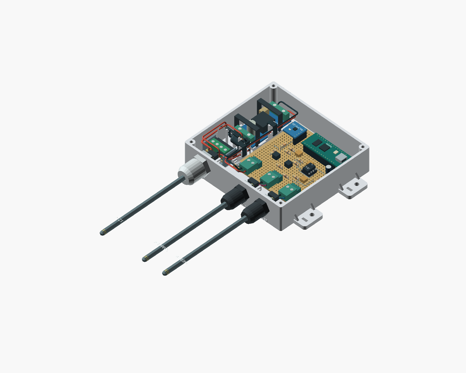
The Yamaha trim project connects the original sensor, acquisition and emulation for the existing gauge. Power, protection, connector dimensions and physical testing matter as much as the software value. The CAD design shows work in progress, rather than a finished installation.
Read the decision in the story02 / DEVELOPMENT
Our path to getting there.
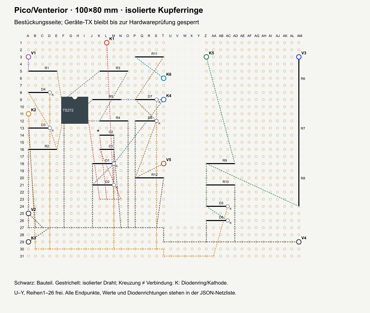
Signal paths are described from the actual connector to their destination. Circuit diagrams, physical layouts and wire data serve different purposes while sharing the same connections.
Actual available parts and their connector variants determine the build. A drawn module does not replace its data sheet or a real measurement.
Digital checks and, where suitable, simulations examine particular subnetworks. A passing software test is not yet an electrical functional test of the physical assembly.
03 / RESULTS
What exists today.
- Circuit, part and enclosure sources exist for the Yamaha trim adapter.
- The sonar build has connection and power designs with physical wiring data.
- Unconfirmed values and real electrical test gaps are identified in each revision.
Images show the development revisions identified in their captions. Today’s source may be newer than an existing image.